Ideas from Ed: Outlet Bonanza
- LCP4P

- Apr 1, 2019
- 5 min read
Updated: Nov 23, 2020
Ed is a do-it-yourselfer who is happy to share some of his ideas and experiences in this monthly column.
Sometimes you just plain need an electrical outlet in the darndest place. Of course, it would be wonderful if every wall would lend itself to fishing wiring through it, that there would be a good source of power somewhere nearby so you don’t need to tear too much apart, etc. Other times, there might not be much you can do other than run wiring along a wall, disguising it as best as you can using raceways. That’s the case in the situation I’m showcasing here. The walls are plaster over lath, and the supply source is a long horizontal distance away, around 2 corners and an outside wall. Raceways are certainly not the most attractive option, but if you locate them well, and possibly paint them to match the background color, they may be tolerable. Here’s the wall location crying for an outlet, and I’d like to put one on the other side of this same wall, roughly a foot away from this spot (so in a different wall cavity between studs.)

Below is a picture of the outlet which will serve as the source of supply. Note that I have already installed a raceway below it which will be painted to match the baseboard. The procedure I’ll show at least makes the outlets look recessed and “normal”, rather than using those large protruding outlets which are commonly used with raceways, but look like bumps on a wall. Raceways running vertically on walls to outlets are much more noticeable than horizontal ones in or against things like a baseboard.

There’s one more thing to note in the picture above. Although you can see where the wiring from the outlet enters the raceway about midpoint, then runs to the right, I extended the raceway all the way against the wood block at the left end of the baseboard. With it running that whole length, it’s less noticeable than one that would start “in the middle”. Once painted, it will hardly be seen at all. SO, let’s go back to your desired location and make sure you don’t want to install an outlet directly over a stud. The best stud-finding procedure, especially with plaster/lath walls where most normal studfinders fail, is to use neodymium magnets. (I won’t go into detail here because you can find several excellent videos online that demonstrate this method.)
OK. You’re pretty sure there’s nothing in the wall (stud, wiring, plumbing, heating ducts, etc.) so the next step is to mark the wall with the location of an outlet box. I’d suggest measuring the height of an existing one and making yours match. Here I’m holding a plastic box with flip-up “ears” against the wall, and using a small level to assure that it is plumb:

This style of box works really well in drywall walls, which are typically thin enough so that as you tighten the screws holding those 2 corner fins, they swivel up and hold the box in place from behind. No additional securing is necessary. On a plaster/lath wall, the fins don’t sit far enough back to get behind the greater wall depth. You can try using longer screws in the fins than what came with the box, or you can forget the flip-up fins and just screw the box to the lath behind the plaster. That means you need to be careful that you don’t damage that lath when you’re cutting the opening, because if it pulls away you’ll have nothing to put the screws into!
Anyway, draw the outline of the box MINUS THE TABS on the wall. You need to have those tabs on the face of the wall to anchor the box from the front. Here’s the outline, and you can see how the box minus the tabs should fit into the rectangle shown:

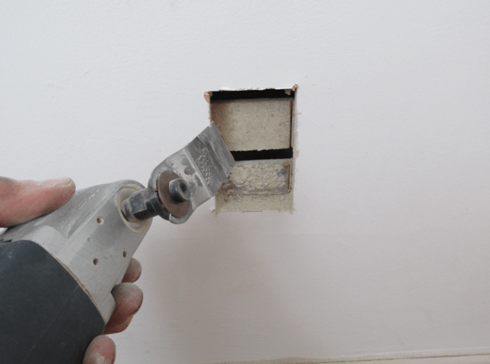
Now you can set up your favorite wall-cutting tool and begin carefully slicing away. I like to use a vibrating multi-tool because no pilot hole is needed, cuts are easy and precise, and it’s just plain fun to use! (That is probably the tool I value most for around-the-home projects, except for a battery-powered drill…)
Here’s the wall opened up:
And, after carefully cutting away the lath within the opening but leaving it around the edges:

You can also see 2 holes where the raceway will go, enabling me to fish wires the short distance between those holes and the outlet. There are TWO holes because, as I said above, I’ll be carrying the wire a bit further along this wall, so I can go through to another outlet on the other side. Tip: Install the raceway first, before drilling the wire hole, and drill through both the raceway and the wall. It will then be invisible once the raceway cover is installed. On my project, the local DIY store was “out” of raceway and I didn’t want to delay the electrical work, so you can ever-so-slightly see the wiring through gaps in the raceway.
Here’s the wire pushed through a hole into the wall, then through the wall opening. Again, in my case, I have another wire that will lead back in a reverse direction and come through the 2nd wall hole, then continue on.

I find it easiest to run the wire into the outlet box, then wire up the outlet, before placing the box into the wall opening. (Read my earlier “Ideas” columns about how to connect wires to outlets, or follow directions that came with the outlet.) Here I’m using a 15 amp receptacle and 14 gauge wire.


In the picture above, I’m also breaking off the “ears” on the outlet assembly. Depending on the situation, and what the outlet is fitting into or against, those will help or hinder you. In my case, there’s a recess in the outlet box into which the outlet (with ears removed) nicely fits.

In the picture above, you can see the 2 dark-colored drywall screws I used to anchor the box into the wall lath. I predrilled the holes before putting the screws in, and angled them slightly, again to help keep from pushing the lath out of position (and then the screw would only be in the plaster.) The raceway usually has a very strong self-adhesive, peel-off backing. I had to cut it to fit nearly up to the wall holes, so now you’ll understand why attaching it first and drilling through it is a better option.

Finally, snap on the cover to the raceway, and in my case, unions to help cover the gaps better.

Sharp eyes will notice that this baseboard is different than the one first shown above, where the source of the power originated. Both were in the same room, but separated by a large built-in “seat/radiator cover”, so that was my point of transition. This end is on the wall, and will be wall-color, while the first section was on the baseboard, and will be painted to blend in with the wood there. Notice again that the raceway runs to the end of the wall/baseboard section, rather than ending where the wire goes through the wall. Much nicer that way!
I hope all your projects go well. Thanks for reading, and happy restoring!
Ed


Comments